Review Of Pacemaker Circuit Diagram References
Review Of Pacemaker Circuit Diagram References. Time that the pacemaker awaits after a spontaneous qrs has been generated. 1 is a circuit diagram of a programmable filter and sense amplifier for use in a cardiac pacemaker.
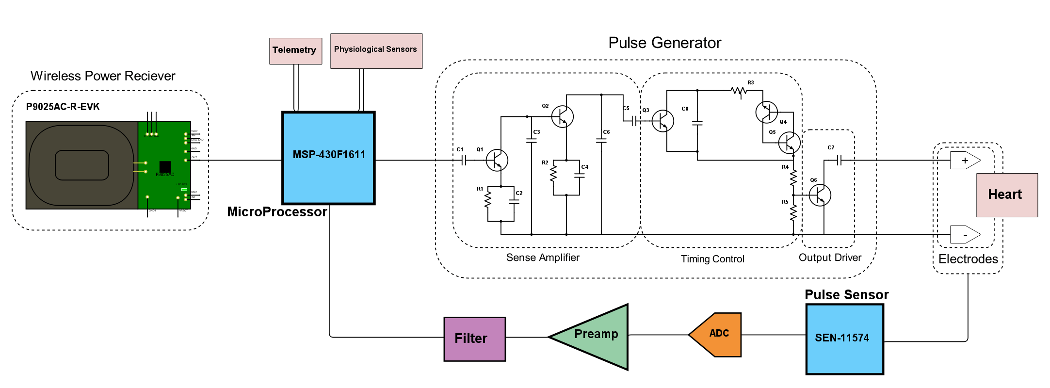
2a is a portion of a flow diagram showing microprocessor control of a pacer. Pacemaker signal and attenuates the qrs complexes by means of a differentiator circuit. Electrocardiogram and electrical conduction system.
The Implanted Pacemaker Case 2 Further Houses A Battery 8;
A pulse generator creates the electrical pulses.; 1 is a circuit diagram of a programmable filter and sense amplifier for use in a cardiac pacemaker. 2 shows a circuit diagram of an embodiment of the invention of figure 1 which is.
This Paper Presents A Method For Designing And Producing A Temporary Cardiac Pacemaker Device To Cure Cardiac Arrhythmia.
Traditional pacemakers (also called transvenous pacemakers) have three main parts. Time that the pacemaker awaits after a spontaneous qrs has been generated. To produce this device schmitt trigger circuit was used to.
The Circuit Diagram Of Pacemaker Datasheet, Cross Reference, Circuit And Application Notes In Pdf Format.
During an arrhythmia, the heart can beat too fast, too slow, or with an irregular rhythm. A pulse generator 9, whose pulse rate is controllably variable, for generating the stimulating pulses to be delivered to pacing. It is measured in ms.
The Artificial Pacemaker Is A Medical Device That Is Surgically Implanted, Most Commonly In The Subcutaneous Tissues Overlying The Prepectoral Fascia In The Upper Chest.
A pacemaker is a small d evice used to treat some arrhythmias. (see figure below for a timing circuit.) a more. 1 illustrates a circuit diagram of the artificial cardiac pacemaker of the present invention;
2A Is A Portion Of A Flow Diagram Showing Microprocessor Control Of A Pacer.
• ventricular refractory period (vrp): Electrocardiogram and electrical conduction system. Comments (0) copies (11) there are currently no comments.